When it comes to planetary reducers, there are basically three different torque levels they need to manage. The first one is called nominal torque, which basically means how much continuous rotational force the reducer can handle day after day without getting too hot or wearing out prematurely. Most manufacturers rate this based on about eight hours of operation each day as standard practice. Then we have peak torque, which tends to be around double what's considered normal. This happens when motors start up or when loads suddenly change, and typically lasts only two to three seconds before things settle down again. There's also emergency stop torque worth mentioning. This measures the absolute maximum load a system can take during those unexpected stops. But let's face it folks, if this kind of extreme loading becomes regular business, gears will definitely suffer more stress and wear out faster than expected. That's why smart engineers always check these numbers against what their specific applications actually demand over time, making sure everything stays reliable in the long run.
When input torque goes beyond what's rated, it starts causing gradual wear on mechanical components. If there's about 10% extra torque applied, the gears tend to bend more, somewhere around 12 to maybe even 18 percent increase in deflection. This makes them much more likely to develop those annoying pits and micro pits we see in simulations from last year. The bearings take a real beating too, especially those tapered roller ones. They have to handle way more load when torque gets high, which cuts down their lifespan by roughly 40%. For anyone wanting parts that last longer, matching motors and reducers properly matters a lot. Keeping peak torque at or below 85 to 95% of what the reducer can handle seems to be the sweet spot according to most field reports.
Output torque is calculated using the formula:
T_out = T_in × i × η
Where:
For example, a 10 Nm input through a 10:1 reduction with 96% efficiency produces 96 Nm at the output. However, thermal losses from sustained high loads reduce efficiency by 0.5–0.7% per 20°C temperature rise, necessitating derating in continuous-duty applications to avoid lubricant breakdown and component failure.
Studies on gear materials show that helical gears can handle about 30 to 50 percent more torque than standard spur gears when used in similar planetary arrangements. What makes this possible? The teeth are cut at an angle rather than straight, so they mesh together progressively instead of all at once. This gradual engagement spreads out the force over several contact points, which cuts down on sudden shocks during operation. When manufacturers bump up the helix angle from around 12 degrees to 15 degrees, they typically see torque handling improve by roughly 17 to 20 percent. Plus, machines run quieter too, with noise levels dropping as much as 10 decibels. These advantages make helical gears particularly attractive for applications where both power transmission efficiency and reduced mechanical stress matter.
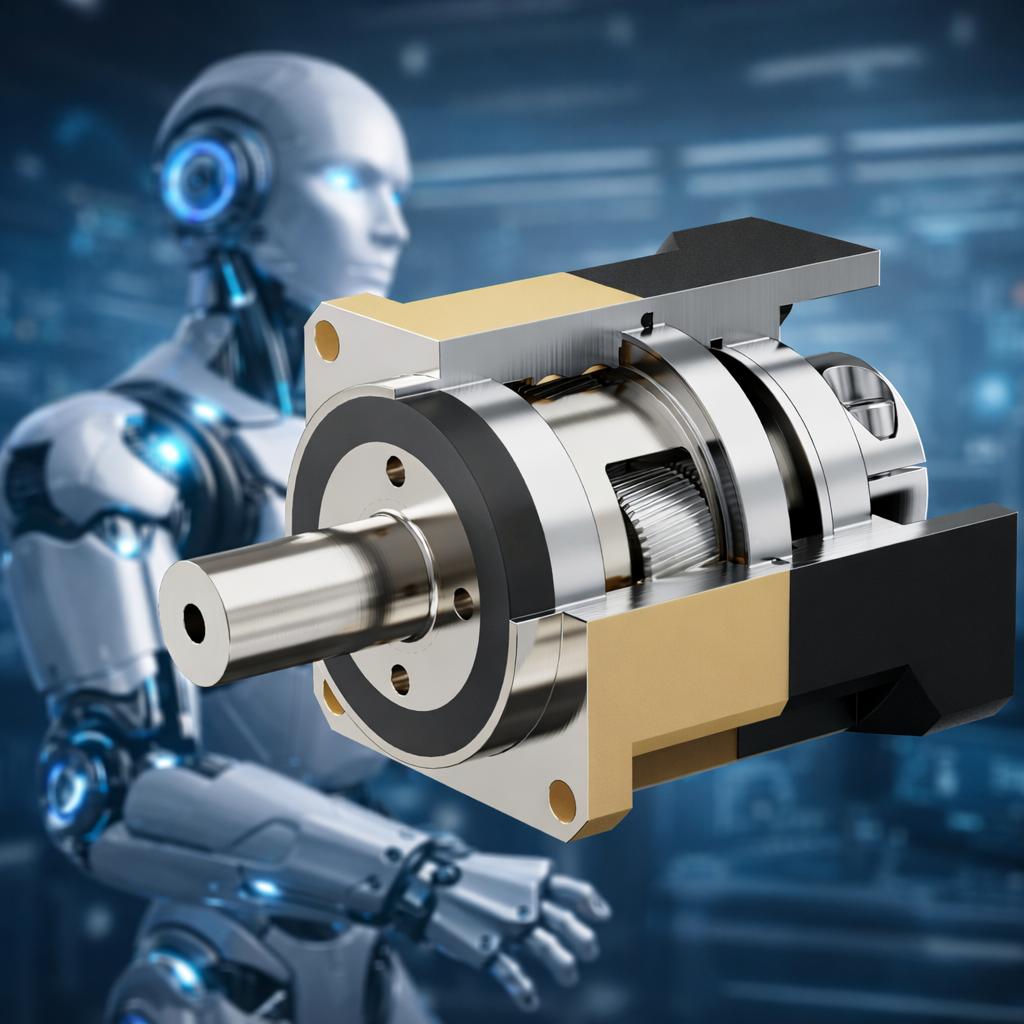
This design enhances both power density and acoustic performance, making it ideal for precision automation and heavy machinery.
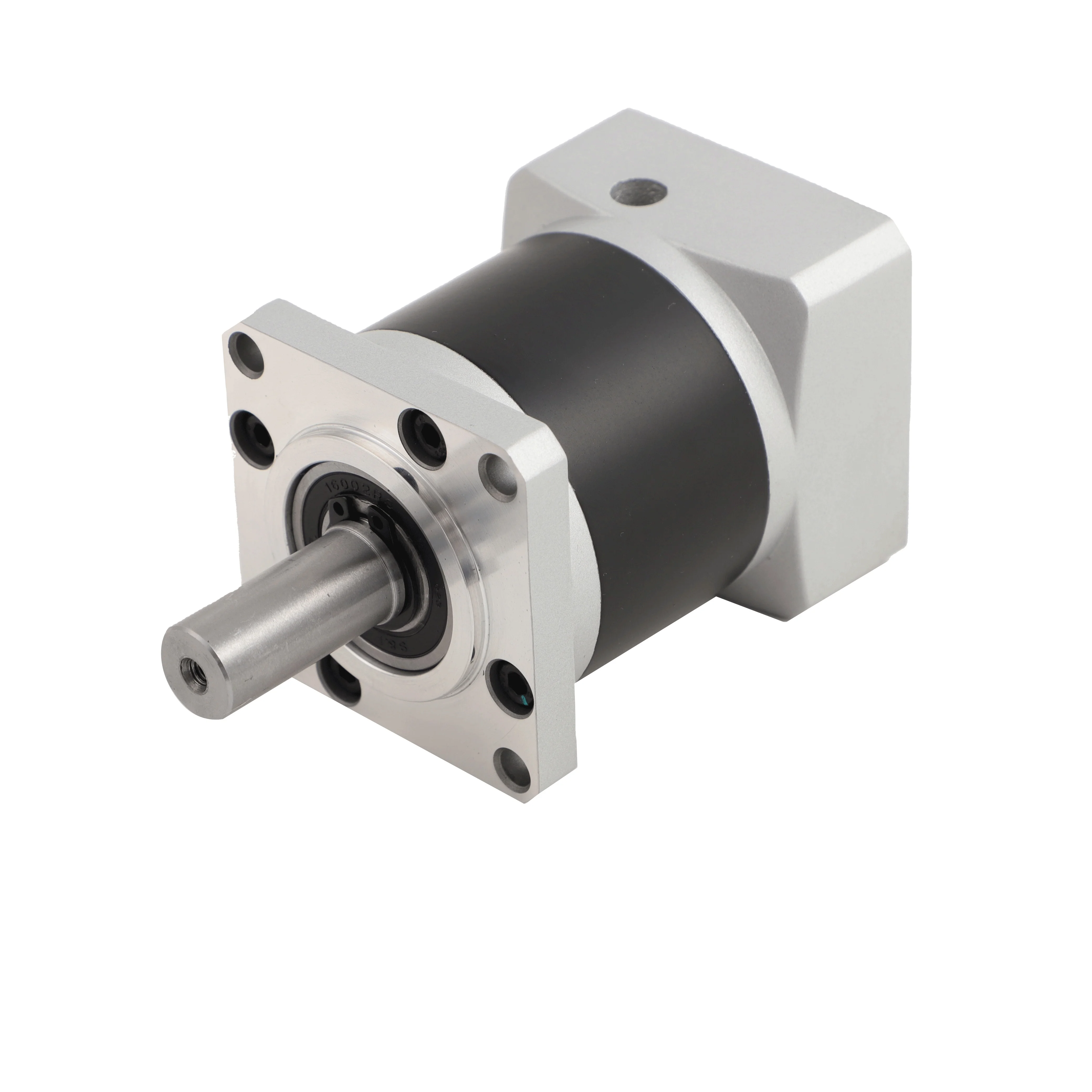
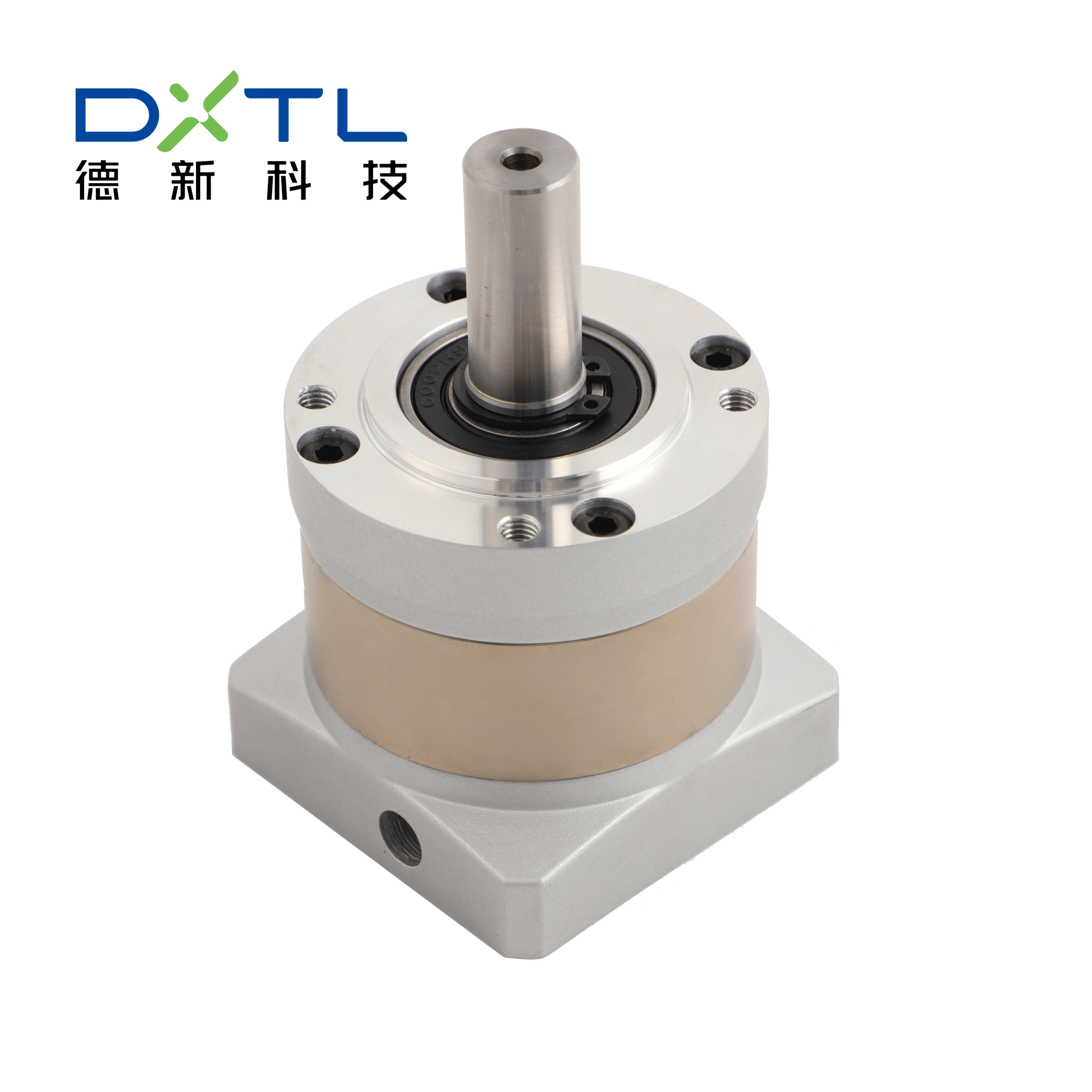
When it comes to planetary reducers handling over 7,500 Nm torque, dual tapered roller bearings really step up their game, boosting torsional rigidity by around 54%. These bearings support the output shaft at both ends, which helps cut down on radial deflection problems that otherwise lead to those pesky issues like edge loading and gear pitting over time. Real world testing has shown that these dual bearing setups can keep positioning accuracy tight within plus or minus 1 arc minute, even when faced with massive shock loads of up to 12,000 Nm. That kind of performance makes them absolutely critical for heavy duty equipment such as crane hoists and mining conveyors where maintaining precision matters most during those intense dynamic operations.
For high torque planetary reducers, the housing needs walls that are around 25 to 40 percent thicker compared to regular models if they're going to hold up against elastic deformation when loaded. Studies using finite element analysis reveal something interesting: ribbed aluminum housings constructed from EN AC-42100 alloy can handle bending forces that are 32% stronger than what cast iron versions manage, plus they save quite a bit in weight. When it comes to mounting surfaces, precision grinding is essential. These surfaces need to be extremely flat, within 0.02 mm per meter tolerance, which stops the housing from warping over time. This attention to detail keeps gears properly aligned during operation and extends how long these components last before needing replacement.
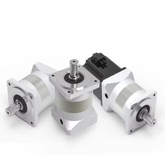
Modern planetary reducers achieve substantial torque multiplication through precise gear ratios and optimized component layouts. Single-stage designs can deliver ratios up to 12:1, while compound stages reach beyond 250:1, enabling compact solutions for high-torque demands.
When looking at how torque works in gear systems, we find that output torque equals input torque multiplied by gear ratio times efficiency. Here's what that means in practice: GR stands for gear ratio while η refers to efficiency levels which usually range from around 94% to 98%. Take a simple example with a 10:1 gear ratio and 100 Nm coming in. Before considering heat losses, this setup would produce somewhere between 940 and 980 Nm going out. The connection between these numbers is pretty straightforward, which explains why gear ratios matter so much when selecting reducers for specific jobs. Getting the right ratio ensures the system performs properly under different conditions without overworking components unnecessarily.
While higher ratios amplify torque, they introduce efficiency penalties and thermal challenges:
| Gear Ratio Range | Torque Gain | Efficiency Drop | Thermal Impact |
|---|---|---|---|
| 3:1 - 10:1 | 3x - 10x | 2-3% per stage | ≈15°C rise |
| 15:1 - 50:1 | 15x - 50x | 5-7% per stage | 20-35°C rise |
| 60:1 - 250:1 | 60x - 250x | 8-12% per stage | 40-60°C rise |
Ratios exceeding 50:1 often require forced cooling or oil circulation systems to manage heat and prevent lubricant degradation during extended operation.
Designers balance four primary factors when selecting gear ratios:
Selecting the right ratio ensures efficient torque delivery without sacrificing lifespan or system responsiveness.
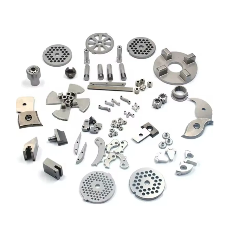
The power transfer starts with the sun gear, driving anywhere from three to seven smaller planet gears positioned around it like spokes on a wheel. How much load each planet takes varies depending on how many there are. When only three planets are used, they generally handle about a third of the total torque each. But when seven planets share the work, the load drops down to roughly 12-14% per gear. Speaking of load capacity, the ring gear plays a crucial role here. Most manufacturers harden these components to around 60-62 HRC to withstand those intense cyclic stresses that can reach over 500 MPa. This level of hardness makes all the difference in heavy machinery applications like excavators and bulldozers, where parts need to keep functioning despite constant changes in workload throughout the day.
There's been quite a discussion lately about how torque gets spread across those planet gears. Some folks in the engineering field actually prefer uneven loading setups where maybe one side takes 35%, another 30%, and then back to 35% again when dealing with linear actuators. They claim this helps keep things from getting too loose over time. But wait - recent tests done last year showed something different happening. When these uneven distributions were put through their paces, components started showing signs of wear much faster than expected, around 12 to even 18 percent quicker in some cases. On the flip side, when torque is shared equally between all parts, we've seen real improvements in how systems handle sudden impacts. Robotic arms using this approach can take shocks better by about 15 percent compared to others. This kind of goes against what many people thought before and makes a strong case for going with balanced designs whenever reliability matters most.
In high torque planetary reducers, case hardened steel alloys are still going strong as the industry norm. These materials reach surface hardness levels above 60 HRC which helps them handle shear stresses well beyond 2000 Nm. The carburized version of 20MnCr5 steel gives about 18% better fatigue resistance compared to traditional 18CrNiMo7-6 according to ASM research from last year. This makes components last longer when put through tough operational cycles. When dealing with corrosive conditions, manufacturers often turn to duplex stainless steel 1.4462. It packs around 1100 MPa tensile strength and stands up pretty well against chlorides too. But there's a catch. This material costs roughly 12 to 15 percent more than regular carbon steels, so engineers have to weigh that extra expense against the potential benefits for their specific application needs.
Precision gas nitriding forms a 0.3–0.5 mm diffusion layer on gear flanks, improving micropitting resistance by 40% in continuous operation (ASTM 2021). Dual-frequency induction hardening allows localized hardening of ring gear roots to 62–64 HRC without compromising core ductility–essential for surviving transient overloads up to 300% of rated torque.
Accelerated testing (AGMA 2023) shows gear sets running at 150% of nominal torque exhibit 73% faster crack propagation. Continuous 8-hour peak operation reduces expected life from 20,000 to 6,500 hours in all-steel configurations. Hybrid ceramic-steel planet gears extend this to 9,200 hours by reducing contact stress and thermal expansion mismatch.
When running at around 90% of their maximum torque capacity, helical planetary gear stages typically achieve efficiencies between 96 and 97 percent. But things change quickly once we go beyond that threshold. Under continuous overload conditions as defined by ISO 14635 standards, efficiency plummets to about 88%. The main culprits here are increased friction and those pesky churning losses that start to accumulate. For every 15% boost in torque past the rated level, operators can expect roughly 22 degrees Celsius extra heat building up in the oil reservoir. This means active cooling becomes absolutely necessary just to keep the lubricant viscosity within safe limits, ideally staying below 65 degrees Celsius to prevent degradation and premature wear on components.
Synthetic PAO-based lubricants with 3% MoS2 additives sustain film strengths up to 2.5 GPa but lose 40% of their anti-wear properties after 1,200 hours under 120% torque loads (FZG 2022). Circulating oil systems with 10-micron filtration extend relubrication intervals by 300% compared to sealed grease-packed units, significantly improving uptime and reducing maintenance costs in high-cycle operations.
 Hot News
2026-06-01
2026-03-24
2026-03-20
2026-03-03
2026-03-02
2026-03-01
Copyright © 2025 by Delixi New Energy Technology (hangzhou) Co., Ltd. - Privacy policy